Introduction
Extruder output calculation is a fundamental part of extrusion engineering. Understanding how it is calculated—and what factors influence it—is essential for: equipment selection, production planning, process optimization, cost control, etc.

This article explains three common approaches for calculating extruder output, each suitable for different application scenarios:
- Actual Output Measurement– The most direct method for determining real production capacity. It is suitable for machine verification, production monitoring, and performance evaluation.
- Geometry-Based Estimation– A practical method for preliminary output prediction based on screw dimensions, speed, and material properties. It is commonly used for equipment selection, capacity comparison, and initial design.
- Advanced Theoretical Modeling – A more detailed approach that considers melt flow mechanisms, including drag flow, pressure flow, and leakage flow. It is mainly used for screw design, process optimization, and high-accuracy output analysis.
What Is Extruder Output?
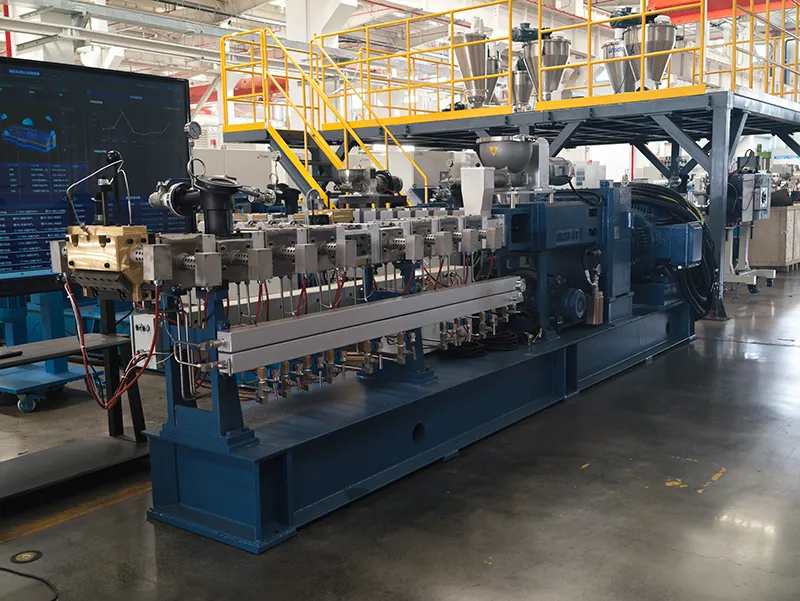
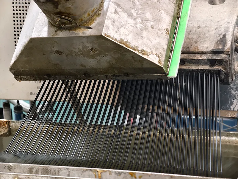
Extruder output refers to the amount of material that an extruder can process and discharge within a given time. It is one of the most important indicators for evaluating extrusion capacity and is commonly expressed as kg/h.
Depending on the calculation method, extruder output can be described in two forms: mass flow rate and volumetric flow rate.
Mass Flow Rate Units
Mass flow rate is the most common way to specify the production capacity of industrial extrusion equipment because it directly represents the amount of material produced.
| Unit | Description | Typical Application |
| kg/h | Kilograms per hour | Standard unit for plastic extrusion equipment worldwide |
| lb/h | Pounds per hour | Commonly used in North America |
| t/h | Tons per hour | Used for large-capacity extrusion systems |
| kg/s | Kilograms per second | Mainly used in engineering calculations and research |
Volumetric Flow Rate Units
Volumetric flow rate describes the volume of polymer melt transported through the extrusion system per unit time. It is commonly used in theoretical output calculations because screw conveying behavior is based on material displacement inside the screw channel.
| Unit | Description | Typical Application |
| m³/h | Cubic meters per hour | Engineering calculations and extrusion system analysis |
| cm³/s | Cubic centimeters per second | Laboratory measurement and flow analysis |
| in³/s | Cubic inches per second | Used in some theoretical calculations, especially in North American engineering references |
The relationship between volumetric flow rate and mass flow rate is:
Mass Flow Rate (kg/h) = Volumetric Flow Rate (m³/h) × Melt Density (kg/m³)
or:
Output = Q × ρ
Where:
- Q– Volumetric flow rate (m³/h)
- ρ– Polymer melt density (kg/m³)
Since polymer density changes with temperature and pressure, theoretical calculations usually first determine the volumetric flow rate and then convert it into mass output using the corresponding melt density.
How to Measure Actual Extruder Output?
Theoretical calculations provide an estimate of extruder output, but the actual production rate should always be verified through measurement. In industrial production, extruder output is typically measured using either offline weighing or online continuous monitoring, depending on the production requirements.
1. Offline Weighing Method
The offline weighing method is the simplest and most widely used approach for measuring actual extruder output. It is commonly used during machine acceptance testing, process validation, and routine production checks.
Measurement Procedure
- Operate the extruder under stable processing conditions.
- Collect all extruded material over a fixed sampling period (typically 60 seconds).
- Weigh the collected material using a calibrated scale.
- Convert the measured weight into an hourly output.
Calculation Formula
Output (kg/h) = Sample Weight (kg) × 3600 ÷ Sampling Time (s)
Example
If 12 kg of material is collected in 60 seconds:
Output = 12 × 3600 ÷ 60 = 720 kg/h
To improve measurement accuracy, the test is usually repeated several times, and the average value is used as the final result.
| Advantages | Limitations |
| Simple and inexpensive | Cannot provide continuous monitoring |
| High measurement accuracy | Requires manual sampling |
| Suitable for machine verification | Cannot detect real-time production fluctuations |
2. Online Continuous Measurement
For continuous production, modern extrusion lines increasingly use online measurement systems to monitor output in real time. The most common solution is a loss-in-weight feeder, which continuously measures material flow using load cells.
Instead of measuring the extruded product directly, the system monitors the rate at which material leaves the hopper. The controller continuously calculates the mass flow rate and automatically adjusts the feeder speed to maintain the target throughput.
A typical online measurement system consists of:
- Material hopper
- Load cells
- Feeding screw or feeder
- Controller with flow calculation and automatic feedback
Compared with manual weighing, online systems provide continuous production data, making them suitable for automated production lines and closed-loop process control.
| Advantages | Limitations |
| Real-time output monitoring | Higher equipment cost |
| Automatic data collection | Requires periodic calibration |
| Supports automatic process control | Measurement may be affected by vibration if not properly compensated |
Note: Modern online weighing systems use digital filtering and signal compensation techniques to minimize the influence of vibration, material refilling, and environmental disturbances, ensuring stable and accurate flow measurements.

3. Offline vs. Online Output Measurement
| Method | Accuracy | Real-Time Monitoring | Investment Cost | Typical Applications |
| Offline Weighing | High | No | Low | Machine acceptance, process validation, periodic inspections |
| Loss-in-Weight Feeder | High | Yes | Medium to High | Continuous production monitoring and automatic process control |
Geometry-Based Estimation of Extruder Output
Engineers often estimate extruder output based on screw geometry, operating conditions, and material properties. These methods provide a quick way to evaluate the theoretical conveying capacity of an extrusion system and are widely used for extruder design and selection.
Although geometry-based estimation cannot fully represent the complex flow behavior during extrusion, such as pressure flow, leakage flow, and polymer rheology effects, it provides a practical reference for comparing machine capacity and predicting output performance.
1. Geometric Parameter Method
The geometric parameter method estimates extruder output by calculating the theoretical conveying volume generated by the screw channel geometry. The screw channel cross-sectional area, screw lead, and screw speed are used to determine the material volume transported per unit time, which is then converted into mass output using melt density.
Formula:
Q = ρ × A × P × N × η
Where:
- Q– Mass output (kg/h)
- ρ– Melt density (kg/m³)
- A– Screw channel cross-sectional area (m²)
- P– Screw lead (m/rev)
- N– Screw speed (rev/h)
- η– Conveying efficiency or correction factor
This method directly shows how screw design parameters affect output:
- A larger screw diameter generally provides a larger conveying volume.
- A higher screw speed increases the number of conveying cycles per unit time.
- A larger screw lead increases the theoretical material displacement per revolution.
However, this calculation represents an ideal conveying condition and does not account for factors such as die resistance, pressure-induced backflow, or leakage flow.
2. Geometric Volume Method
When the theoretical conveying volume per revolution is known, the output calculation can be simplified using the geometric volume method.
Formula:
Q = Cv × N × ρ × η
Where:
- Q– Mass output (kg/h)
- Cv– Theoretical conveying volume per revolution (m³/rev)
- N– Screw speed (rev/h)
- ρ– Melt density (kg/m³)
- η– Correction factor
The geometric volume method is essentially a simplified form of the geometric parameter method. The value of Cv is calculated from the screw channel geometry and represents the theoretical volume transported during one screw revolution.
The difference between the two approaches is mainly how the conveying volume is expressed:
- Geometric parameter method:Calculates conveying volume from screw dimensions, such as channel area and lead.
- Geometric volume method:Directly uses the calculated conveying volume per revolution.
Both methods are commonly used for preliminary capacity estimation and extrusion equipment comparison.
3. Limitations of Geometry-Based Estimation
Although geometry-based estimation provides a convenient way to predict extruder output, it is based on ideal conveying assumptions and cannot fully describe actual extrusion conditions.
In real production, the output can be affected by:
- Die and filter pressure resistance
- Pressure flow inside the screw channel
- Leakage flow caused by screw–barrel clearance
- Polymer viscosity and rheological behavior
- Feeding stability and screw wear
Therefore, the output calculated by geometry-based methods is usually higher than the actual production rate.
To better understand how these factors influence material flow, more advanced extrusion flow models consider drag flow, pressure flow, and leakage flow effects.
Advanced Theoretical Models for Extruder Output Calculation
Geometry-based estimation provides a quick method for calculating extruder output based on screw dimensions and operating speed. However, it mainly represents the ideal conveying capacity of the screw and does not fully consider the flow losses occurring during actual extrusion.
For more accurate output prediction, extrusion theory analyzes the melt flow inside the screw channel. By calculating the contribution of drag flow, pressure flow, and leakage flow, engineers can estimate the net volumetric flow rate and then convert it into mass output (kg/h) using melt density.
The simplified relationship can be expressed as:
Q = QD − QP
When leakage loss is considered:
Q = QD − QP − QL
Where:
- Q– Net volumetric flow rate, representing the theoretical melt throughput inside the extruder. It can be converted into mass output (kg/h) by multiplying by the melt density.
- QD– Drag flow generated by the relative movement between the screw and barrel. It represents the forward conveying capacity and is usually the main contributor to extrusion output.
- QP– Pressure flow caused by melt pressure generated by die resistance and downstream restrictions. It acts in the opposite direction to drag flow and reduces the net output.
- QL– Leakage flow caused by the clearance between the screw flight and barrel wall. It represents additional material loss, which may increase as screw and barrel wear develops.
Influence of Polymer Rheology
The drag flow and pressure flow model is commonly based on simplified assumptions, such as constant viscosity and Newtonian fluid behavior. However, most polymer melts used in extrusion are non-Newtonian fluids, and their viscosity changes with shear rate and temperature.
Most thermoplastic melts exhibit shear-thinning behavior, meaning their apparent viscosity decreases as shear rate increases. Therefore, the same extruder operating under identical screw speed and pressure conditions may achieve different output rates when processing different materials.
In practical output calculations, engineers need to consider material rheological properties, including melt viscosity, processing temperature, and material formulation. For high-accuracy prediction, rheological data from material testing or simulation software may be incorporated into the model.
Factors Affecting Extruder Output
Extruder output is influenced by several key factors, including equipment design, operating parameters, material properties, and die resistance.
| Category | Key Factors | Main Effect on Output |
| Equipment | Screw diameter, screw design, L/D ratio, screw wear | Determines conveying capacity and efficiency |
| Processing | RPM, temperature, back pressure, feeding stability | Controls actual operating performance |
| Material | Density, viscosity, rheology, moisture, filler content | Affects flow behavior and stability |
| Die & Downstream | Die resistance, product geometry | Influences pressure loss and net output |
FAQ About Extruder Output Calculation
Does increasing RPM always increase extruder output?
No. Increasing screw speed usually increases extruder output, especially at lower speed ranges, because higher RPM increases the conveying capacity generated by drag flow.
However, the relationship is not always linear. At higher speeds, factors such as increased melt pressure, pressure flow, shear heating, reduced conveying efficiency, and feeding limitations may slow down output growth.
For twin-screw extruders, especially those using starve feeding, output is often controlled by the feeding rate rather than screw speed alone. Therefore, increasing RPM without increasing feed rate may have limited effects on actual throughput.
Why is actual extruder output lower than the rated output?
The rated output provided by manufacturers usually represents the performance achieved under specific test conditions, including:
- Specific material;
- Screw configuration;
- Screw speed;
- Temperature settings;
- Die conditions.
Actual production output may be lower due to differences in:
- Material properties and viscosity;
- Die resistance and melt pressure;
- Feeding stability;
- Processing temperature;
- Screw and barrel wear.
Therefore, rated output should be considered as a reference value rather than a guaranteed production rate for all applications.
Can the same output calculation formula be used for single-screw and twin-screw extruders?
Not exactly.
Basic flow concepts such as drag flow, pressure flow, and leakage flow apply to both types of extruders. However, twin-screw extruders have more complex material transport due to screw intermeshing, screw elements, and filling conditions.
Single-screw extruders can often use simplified analytical models, while twin-screw output prediction usually requires more advanced simulation and experimental verification.
What is the difference between theoretical output and actual output?
Theoretical output is the calculated capacity based on ideal conditions and machine parameters, while actual output is the real production rate measured during operation.
Actual output is usually lower due to factors such as material properties, die resistance, feeding conditions, and equipment wear.