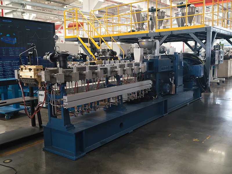
A twin screw extruder is one of the most important processing machines used in plastics compounding, masterbatch production, polymer blending, and recycling industries. But how does a twin screw extruder work? What are the main parts of a twin screw extruder? And why is it more efficient than a single screw extruder? In this guide, we explain the working principle, key components, and processing stages of a modern co-rotating twin screw extruder.

1. What Is a Twin-Screw Extruder?
A twin-screw extruder is a continuous-process machine that uses two intermeshing, rotating screws to continuously feed, melt, plasticize, shear, mix, degas, and shape materials.
The twin-screw extruder is an upgraded version of the single-screw extruder. It overcomes the shortcomings of the single-screw extruder, such as poor feeding and inadequate plasticization, making it one of the most widely used core pieces of equipment in the plastics processing industry today.
Major applications include:
- Filling and reinforcement modification
- Blending and alloying
- Coloring and masterbatch production
- Reaction extrusion
- Devolatilization and degassing
- Direct extrusion molding
2. Key Parts of Twin-Screw Extruders
To gain a thorough understanding of how twin-screw extruders work, we must first grasp the composition and functions of their core components. These components work in concert to form the complete processing path that transforms material from a solid state into an ideal melt and ultimately into a finished product.
① Screw System
The design and configuration of the screw system directly determine the equipment’s processing capacity and the final quality of the product. In modern industrial applications, the co-rotating intermeshing twin-screw configuration has become the mainstream. In this configuration, the two screws rotate in the same direction, and the flutes of one screw are tightly interlocked with the grooves of the other, providing excellent material transfer and self-cleaning performance.
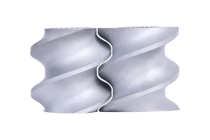
Modular Design:
The screws of a twin-screw extruder are composed of a series of screw elements with different functions, connected in series via a spline shaft to achieve functions such as conveying, shearing, plasticizing, and mixing.
Engineers can freely combine screw elements like “building blocks” based on different material systems and process objectives (such as mixing, melting, and degassing) to customize the most suitable screw configuration.
Functional Classification of Screw Elements:
Screw elements can be broadly classified into the following categories based on their geometric shape and function:
- Conveying/Feeding Elements
- Kneading/Mixing Elements
- Reverse and Restrictive Elements
- Special Elements (Side Feeder Elements, Venting Elements, High Free Volume Elements, Low-Shear Elements)
② Barrel System
The barrel provides the screw with a sealed, temperature-controlled processing space and works in close coordination with the screw system to process the material.

Modular Structure:
Similar to the screw, the barrel of a modern extruder also employs a modular design, consisting of multiple independent barrel sections connected together, which can be flexibly configured according to process requirements.
Functional Interfaces:
The modular structure of the barrel makes it possible to install functional interfaces at different locations:
- Main Feed Port:Typically located in the first barrel section, used for adding resin, primary additives, and other materials.
- Vent/Vacuum Port:Located in areas where outgassing is required; can be connected to atmospheric or vacuum systems.
- Side Feed Port:Used to add shear-sensitive fillers (such as long glass fibers) or liquid additives after the material has melted, to prevent excessive damage during the initial melting stage.
- Liquid Injection Port:Used to inject liquid additives, reactant monomers, or water (for steam injection processes).

③ Drive System: Gearbox & Drive System
The drive system delivers stable torque and adjustable rotational speed to the screw via a motor and a high-torque gearbox, ensuring stable power output throughout the entire processing cycle.


Drive Motor: Modern extruders generally use AC variable-frequency motors or more efficient permanent magnet synchronous motors, which enable stepless adjustment of screw speed via a variable-frequency drive. This allows operators to precisely control shear rate and output according to process requirements.
High-Torque Gearbox: This is the core of the drive system and one of the components with the highest technical barriers. It has two primary functions:
- Speed Reduction and Torque Multiplication:It reduces the motor’s high rotational speed to the process speed required by the screw (typically ranging from tens to thousands of revolutions per minute), while multiplying the torque several times over to overcome the immense resistance caused by high-viscosity melt.
- Power Distribution:It precisely distributes power from a single motor to two parallel screw shafts and ensures they rotate synchronously in the same direction.
Higher specific torque allows:
• Higher throughput
• Higher filler loading
• Lower energy consumption
• Better process flexibility
④ Feeding System
The feeding system is responsible for continuously feeding material into the extruder’s main or side feed port in a stable and controlled manner.

Types:
- Volumetric Feeder:Conveys material at a constant volumetric rate via a screw or belt. It features a simple structure and lower cost, but its accuracy is significantly affected by variations in the material’s bulk density.
- Gravimetric Feeder / Loss-in-Weight Feeder:Monitors the rate of material weight loss within the feeder in real time using high-precision load cells and adjusts the feed screw speed via a closed-loop control system to maintain a constant mass flow rate.
Gravimetric feeders offer high precision and excellent stability; they are the preferred choice for precision processing and compounding, and are key to achieving precise control of material formulations.
⑤ Heating and Cooling System
The heating and cooling system precisely controls temperature changes within the barrel through zone-based temperature control.
Zone Control: The entire barrel is divided into multiple independent temperature zones, each equipped with heaters and cooling devices.
- Heating:Electric heaters (such as cast aluminum, cast copper, or ceramic heaters) are typically used to transfer heat to the material through the barrel.
- Cooling:When shear-induced heat causes the temperature to exceed the setpoint, the cooling system activates. Cooling methods typically include air cooling and water cooling. Water cooling is highly efficient and provides precise temperature control, making it suitable for processes requiring rapid heat removal.
PID Closed-Loop Control: Each temperature zone is equipped with a thermocouple that monitors temperature in real time and feeds the data back to the control system. The system continuously compares the setpoint with the actual value using a PID algorithm and automatically adjusts the heating power or cooling flow to achieve precise temperature control. Some high-end systems use dual PID controllers to control heating and cooling separately, thereby improving response speed and stability.
⑥ Control System
The control system monitors, adjusts, and performs closed-loop control of all process parameters via a PLC (Programmable Logic Controller) and an HMI (Human-Machine Interface, typically a touchscreen).
The PLC is responsible for executing low-level logic control and closed-loop regulation, while the HMI provides an intuitive graphical interface for parameter setting, status monitoring, alarm display, and data logging.

3. Twin Screw Extruder Working Principle
The overall working principle of a twin-screw extruder can be succinctly summarized as follows: Through two co-rotating, meshing screws, the twin-screw extruder applies both conveying and shearing forces to the material. Combined with external heating and heat generated by internal shearing, this enables the material to continuously transition from a solid state to a uniform melt and be extruded in a stable manner.
The following describes the main process of material movement within a twin-screw extruder, from the inlet to the outlet, from the material’s perspective. The entire process can be divided into five core stages based on changes in material form and the primary physical processes involved:
① Material Conveying and Initial Pressurization
This is the first stage after the material enters the extruder. Solid particles or powders enter the barrel via the feeding system and are continuously conveyed forward within an approximately “C-shaped filled zone” formed by the screws. As the material is gradually compacted, the system begins to build initial pressure, laying the foundation for subsequent melting, mixing, and stable extrusion.

② Melting and Plasticization
This is the stage in the entire process that consumes the most energy and undergoes the most significant physical transformations. The material gradually heats up and begins to melt under the combined effect of external heating and internal shear heat generated by the screw. Solid particles are gradually transformed into a uniform melt, completing the plasticization process. By controlling the temperature and screw speed, the material can be fully melted and a stable melt state achieved.

③ Dispersive and Distributive Mixing
The melted material enters the mixing stage, where various resins, fillers, pigments, and additives are uniformly distributed through repeated breakup and re-dispersion. Shear forces break up agglomerates of fillers or additives, improving dispersion uniformity.
④ Venting and Devolatilization
For material systems containing moisture, residual monomers, or reaction by-products, a venting zone is typically incorporated to remove these substances. This prevents defects such as bubbles and silver streaks in the final product and improves product performance. During this stage, moisture and volatile substances are removed from the melt through depressurization, surface renewal, and vacuum extraction.

⑤ Homogenization, Pressure Buildup, and Die Forming
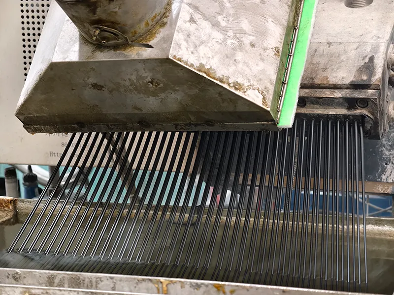
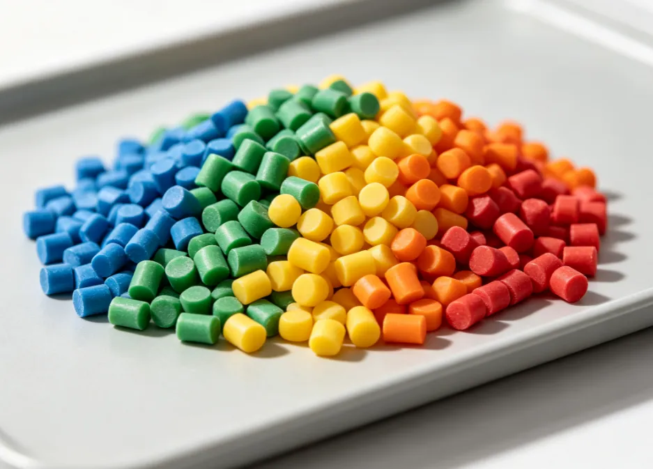
Before leaving the extruder, the melt is further homogenized at the outlet and stabilized under pressure. It is then continuously extruded through the die, followed by cooling and pelletizing to form the final product.

Conclusion
In summary, the twin-screw extruder achieves highly efficient and controllable material processing through the coordinated action of its key components—screw system, barrel system, drive system, feeding system, heating & cooling system, and intelligent control system.
Why Choose KYmach Twin Screw Extruders?
KYmach has specialized in twin screw extrusion technology since 1993 and provides:
- Laboratory Twin Screw Extruders
- Compounding Extrusion Lines
- Masterbatch Production Lines
- Biodegradable Plastic Extruders
- High-Torque Twin Screw Extruders
- Complete Turnkey Solutions
With more than 11,000 installations worldwide, KYmach supports customers in over 60 countries.
Contact our engineering team for customized screw configuration and process solutions.